Joint Design Manufacturer of

ECU Diagnostic Box
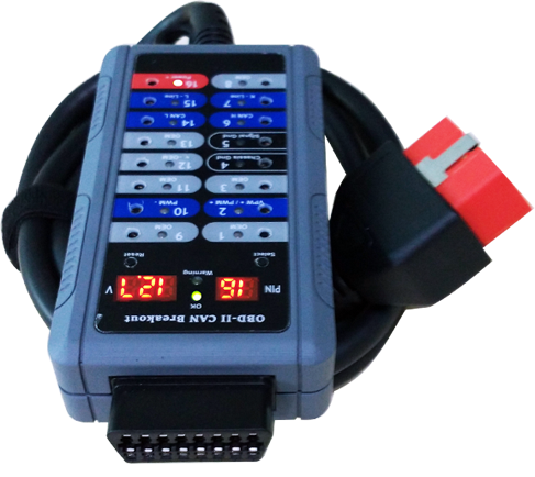
The ECU Diagnostic Box (EDB) is a versatile CAN Bus tester that determines the physical integrity of a CAN Bus by checking its low (CAN-L) and high (CAN-H) line voltages.
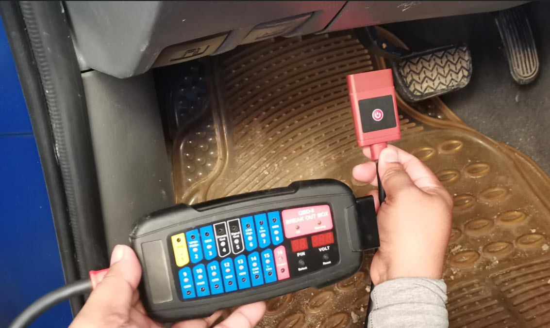
The tool connects directly into the Vehicle’s Data Link Connector (DLC) for testing any abnormalities such as shorting and reverse polarity at the pins. In case the DLC has a short or reverse polarity present, connecting the EDB first will prevent damage to your expensive scan tool.
Exclusive Inventions
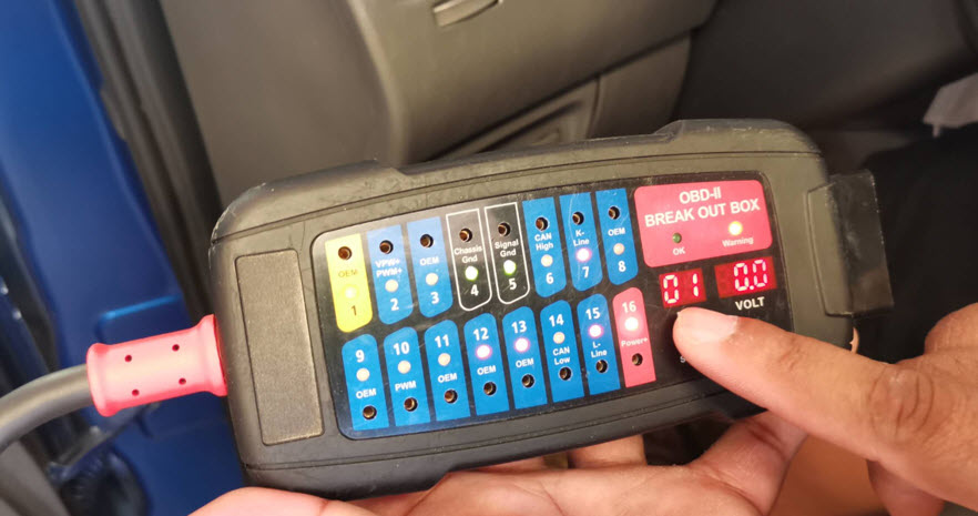
1. Live display of pin signals- this Breakout Box provides a live display of communicating signals without having to use a Digital Multimeter.
2. Pin voltage display- it allows testing the voltages of every pin of Diagnostic Link Connector 14 pins (except pins 4 & 5).
When Select button is pressed, Pin display will change randomly as well as the volt meter display should any voltage present on the selected pins.
Unique Features
Once plugged into the car’s DLC (OBD port), it will start to check the pins for any voltage present.
If voltage is present, the respective LEDs will illuminate as follow:
1. Pins 2, 6, 7, 10, 14, 15- Blue / Red dual color LEDs.
Blue color: Normal protocol communication (pulse) signal.
Red color: Constant Voltage present.
![]()
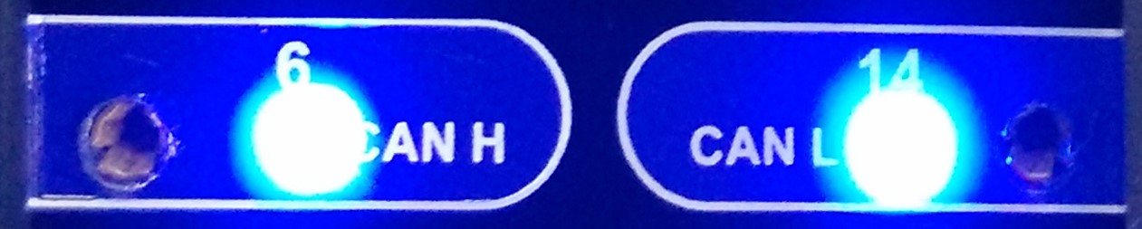
The Blue LEDs will blink when signal voltage detected depends on the communication protocols (Pin 6: CAN H, Pin 14: CAN L), (Pin 2: VPW+ & PWM+), (Pin 10: PWM-), (Pin 7: ISO-9141 K-Line & Pin 15: L-line) present. If constant 12V present on these pins, the LED will stay ON and becomes RED color.
2. Pins 1, 3, 8, 9, 11, 12, 13 Yellow / Red dual color LEDs.
Yellow color: Normal communication (pulse) signal
Red color: Constant Voltage present.
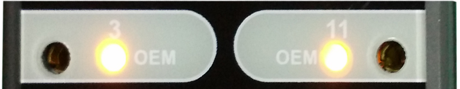
If pulse voltage is detected on any of the pins 1, 3, 8, 9, 11, 12 and 13, its respective LED will turn Yellow and the warning Yellow LED will illuminate as well.
4. Pin 4 & Pin 5- Green / Red dual color LEDs.
Green color: Correct Grounding (-)
Red color: Reversed polarity (+) detected.
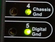
When the ECU Diagnostic Box is plugged into the vehicle DLC and detected reverse polarity in pin 4 and 5, the LED will turns RED color. This indicates incorrect polarity.
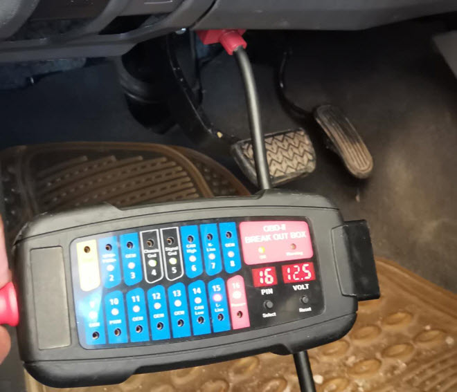
The default Pin display is always set to pin 16 with corresponding battery voltage display on its volt meter
(an example: 12.6V) detected from the DLC.

5. Warning beeps:
Slow Beeps: Below 11.8V /23.6V (Low Voltage)
Fast Beeps: Above 15.5V/31.0V (High Voltage)
Once Pin 16 (Power+) voltage is Low: below 11.8V for 12V system or below 23.6V for 24V system a slow alarm beeps can be heard; otherwise for High voltage: above 15.5V for 12V system, above 31.0V for 24V system will trigger faster alarm beeps as warning.
![]() OK Green LED will illuminate when everything is OK (no short, no voltage present on any pins, reverse polarity, etc)
OK Green LED will illuminate when everything is OK (no short, no voltage present on any pins, reverse polarity, etc)
![]() Warning Yellow LED will illuminate if any of these pins 1, 3, 8, 9, 11, 12, 13 has voltage present on them.
Warning Yellow LED will illuminate if any of these pins 1, 3, 8, 9, 11, 12, 13 has voltage present on them.
![]() RESET button is to restore the default setting wherein pin selection is set to pin 16
RESET button is to restore the default setting wherein pin selection is set to pin 16
![]() SELECT button is use to select pin for testing of any voltage present
SELECT button is use to select pin for testing of any voltage present
Functions
This ECU Diagnostic Box is applicable for 12V and 24V systems.
If there is a need to check voltage of other pins, press SELECT button and the pin numbers will jump 1 at a time then show its corresponding voltage in the volt meter if detected.
Press SELECT button again will continue to pin 2 and so on.
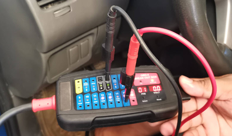
The contact points can be either plugged in for hands free operation or just by surface contact during
measurement with the probes.
Optional Add-ons
· Data Saver Cable
· OBD Y Cable
Specifications
Operating range: 7.0 ~ 30.0VDC Input.
Maximum Load: Up to 3.0 Amps Output.
Overload Protection: Yes- PTC Fuse (Self-healing)
Volt Displays: 3 Digits LEDs (Resolution: 0.1V)
Banana Sockets: 16 outputs x 1.0mm diameter with LED lamp indications.
Protocols Detected: PWM (J1850), VPW (J1850), ISO 9141-2, DIS/ISO 14230-4, Canbus (J-2284).
Operating temperature: 0 Deg.C ~ 50 Deg.C (32 Deg.F~122 Deg.F)
Permitted Humidity: Less than 70%.
OBD cable length: 1.5 meter
Reverse Polarity protection: Yes, LED on pin 4 & 5 turns Red
